Most electrical problems show up not when things are switched on but under load. A clamp meter, battery tester and thermal camera show how a system that looks sound actually works.
Charging readings
- Alternator
- With the engine running, current to the batteries is read with the clamp meter, together with battery voltage.
- Charger
- On shore power, charge current, compared with the rated value.
- Solar and wind
- If fitted, current at the regulator output is noted with the conditions at the time.
Consumption and leakage
- Parasitic draw: current drawn from the batteries with everything switched off. If higher than expected, it explains batteries that run down by themselves.
- Leakage: measured on the DC negative and the AC protective conductor.
- Overload: the current drawn by running equipment, compared with the circuit's fuse and cable size.
Battery test
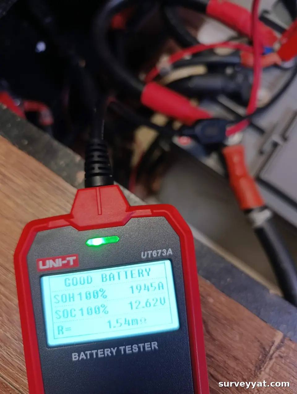
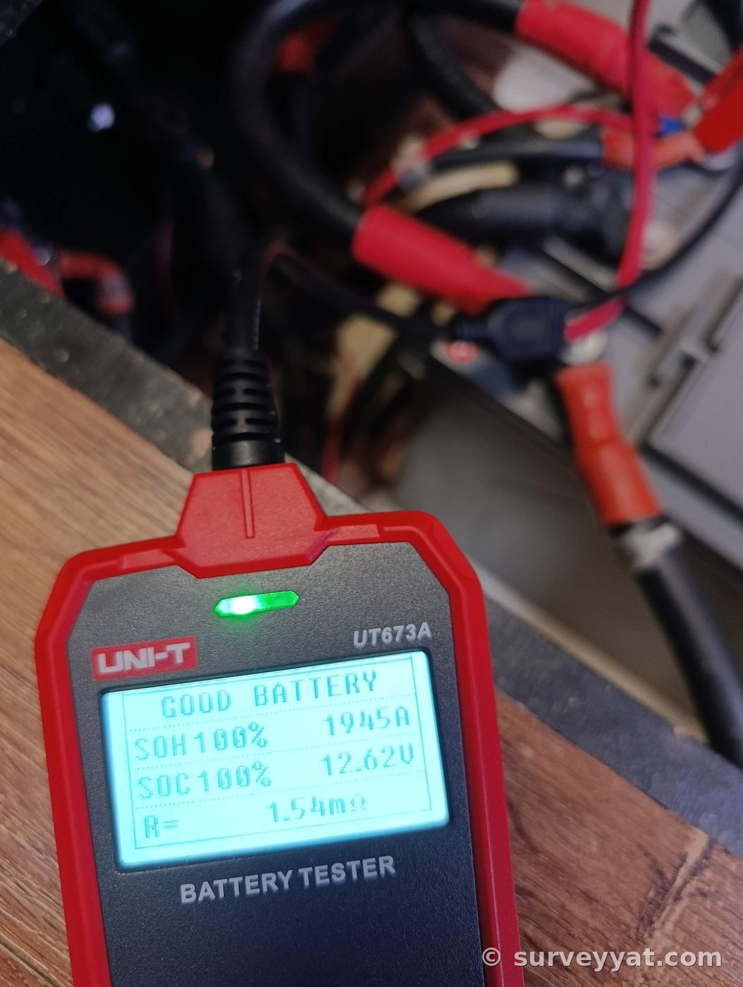
On lead-acid and AGM batteries, internal resistance and cranking capacity are measured; a battery with normal voltage but lost capacity is found this way. On lithium banks, condition is read from the battery management system records.
Hot connections
Switchboard, main switch, battery terminals and high-current circuits are scanned under load with the thermal camera. Hot spots are reported with a photo.
What we often see
- Overheating electrical connection: On the thermal camera, one pole of the main battery switch is markedly hotter.
- Unfused circuit added later: A circuit added for extra equipment in household cable with terminal blocks, and no fuse.
Continue with this topic
- Rewiring: When the readings call for a rewire.
- Battery and charging: Banks and charging sources.
Voltage drop
If the voltage at an appliance is lower than at the batteries, the difference has been lost in cables and connections. It is measured with the appliance running. On sensitive or high-current loads such as the windlass, autopilot and instruments, voltage drop is a common cause of faults and odd behaviour. The result shows whether cable sizes and connections are adequate.
Insulation resistance
An insulation resistance test shows whether cable insulation has deteriorated. On cables left long in damp and cycling through heat and cold, insulation weakens over time. Low insulation resistance can herald a leak or a future short circuit. The test is done with the system off and sensitive equipment disconnected.
Load test
A battery's behaviour under load is measured, not just its voltage. A battery that looks fully charged can drop fast under load. A battery tester gives an idea of remaining capacity. Batteries in a bank should read close to each other; a weak battery drags the healthy ones down.
Charging sources
Each charging source, alternator, shore charger and solar panels, is run on its own and its output measured. Charge voltage is checked against the battery type; a wrongly set charger can wear a battery out quickly.
In the report
All readings are given in a table with their conditions. Where a value is outside the expected range, the finding is written with its grade and the recommended work.
Tools
A true RMS clamp meter, a battery tester and the thermal camera together let most of these readings be taken without disturbing the installation.
Most electrical problems cannot be seen. A cable may look sound while its connection has corroded; a battery may look full while it has lost capacity. Measurement turns the unseen into numbers.
Repeated over the years, the readings also show how the system is ageing, which makes it easier to time maintenance and renewal sensibly.