On a boat, fire most often starts in the electrical installation. Second on the list is something nobody notices: stray current eating the metal. Both are silent, both build over years, and neither shows itself to the eye.
This page sets out how the electrical system is assessed during a survey: which readings are taken, why, and what the numbers mean.
1. DC System: From Battery to Load
The boat's backbone is 12 or 24 volts. Faults here arrive slowly: a connection warms, resistance rises, it warms further.
| Measured | What is looked at |
|---|---|
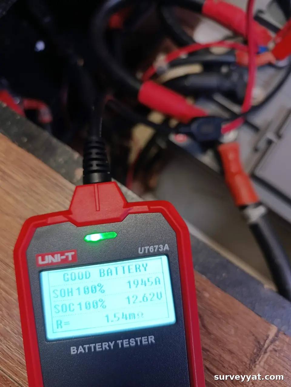
| Battery bank and internal resistance | Capacity test and internal resistance; how closely the cells in a bank match. One failing battery drags the bank down. |
| Alternator charging | Voltage and current under running conditions; whether the charge profile suits the battery type. |
| Charger and bank separation | Start and service banks kept apart, use of diodes or DC-DC. |
| Cable size and voltage drop | An undersized run drops voltage, raises current and heats the cable. ABYC E-11 takes 3% on critical circuits and 10% elsewhere. |
| Fusing and circuit protection | Every circuit protected, fuse rated to the cable, protecting the appliance instead of the cable is a common error. |
| Main battery fuse | Expected within 18 cm of the positive terminal; that short unprotected run is a known starting point for boat fires. |
| Connections and terminals | Oxidation, looseness, crimping versus solder, heat marks. The thermal camera shows this under load. |
2. AC System: Shore Connection
230 V behaves differently afloat: the structure conducts, the environment is wet, leakage goes into the water.
- Residual current device (RCD): present, working, correctly placed. The test button is not enough; trip time is measured.
- Earth continuity: the green conductor unbroken from panel to appliance.
- Galvanic isolator / isolation transformer: the component that blocks galvanic current arriving through the marina earth; presence and integrity checked.
- Polarity and neutral-earth separation: reversed polarity or a neutral-earth bond aboard creates lethal leakage.
- Leakage measurement: current on the earth conductor read with a true RMS clamp meter. It should be close to zero.
- Shore lead and sockets: the lead end, heat marks and burning, the most commonly skipped item.
3. Current Into the Water: The Silent Damage
| Reading | What it means |
|---|---|
| Silver/silver chloride reference electrode | Hull potential in the water. On steel, more negative than −850 mV is expected; on aluminium the band is −950 to −1100 mV. |
| Anode consumption rate | An anode gone in a single season is not normal protection, it signals stray current. |
| Shaft and propeller wear | Faster wear than expected is often the visible face of an electrical problem. |
| Bonding system | Underwater metals tied to a common conductor; a broken link sacrifices that fitting alone. |
See cathodic protection survey for detail.
4. Thermal Camera: Looking Under Load
- The panel is opened and scanned with circuits running.
- An unexpected temperature difference between neighbouring terminals points to a loose connection.
- Alternator, inverter and charger are imaged separately while working.
- Findings enter the report with a photograph and the temperature reading.
5. What Comes Up Most Often
- Unfused additions: equipment added later, tapped into an existing circuit without protection.
- Size mismatch: a large fuse on thin cable, the cable burns before the fuse opens.
- Tangled wiring: no colour code, no labels. When a fault occurs nobody knows what is what.
- Domestic components: household sockets and connectors, which fail quickly in salt air.
- Joints in damp places: splices at bilge level without heat shrink or insulation.
- No galvanic isolator: current from the marina earth consumes anodes quickly.
- Battery ventilation: lead-acid batteries in an unventilated space allow hydrogen to collect.
6. What Changes with Age
| Installation age | What comes to the front |
|---|---|
| 0-8 years | Installation omissions; how later additions were connected. |
| 8-15 years | Battery bank life, terminal oxidation, charger and inverter age. |
| 15-25 years | Cable insulation hardening, panel component life, accumulated added circuits. |
| 25+ years | Assessment of the whole installation becomes the question; piecemeal repair is rarely economic. |
7. What Goes in the Report
Electrical findings carry the same classes as the rest: A, affects safety at sea, not to be gone to sea with; B, planned repair; C, monitor. Each is written with a photograph, the reading taken and the relevant standard reference.
For scope and fee see the survey calculator; if the boat has to be moved, the delivery calculator.

Taken from a real client report (96 pages, issued in Turkish). Boat name, make/model, report number, hull and engine numbers, place, date and people are withheld. More pages from the report
Frequently Asked Questions
Scope: The survey is non-destructive and nothing is dismantled; details on the survey types page.
Findings we often see on site
- Overheating electrical connection: On the thermal camera, one pole of the main battery switch is markedly hotter.
- Unfused circuit added later: A circuit added for extra equipment in household cable with terminal blocks, and no fuse.
- Leakage current on shore power: A steady current measured on the earth conductor with shore power connected.
Continue with this topic
- AC and shore power: RCD, polarity and galvanic isolation.
- Electrical measurements: Charging, draw, leakage, batteries and hot connections.
Related Pages
Send the boat details and what you have noticed; we will set the scope together.
💬 WhatsApp 📝 Written quote 📞 +90 501 5 SURVEY